Employment Application Apply
Understanding how a falling film evaporator works begins with a thin liquid layer moving across heated tube walls. Unlike flooded evaporators, this design feeds liquid from the top and allows gravity to guide it downward. The working principle of falling film evaporator systems depends on controlled distribution, rapid heat transfer, and efficient vapor separation.
A liquid distributor spreads the feed into smooth, continuous films. Inside each vertical tube, steam or another heating medium warms the outer surface. As the liquid descends, part of its solvent evaporates and forms vapor bubbles. The remaining concentrate becomes thicker during its short residence time. Short residence time matters.
At the lower outlet, vapor and concentrated liquid enter a separator. The separator removes entrained droplets before vapor moves toward condensation or the next effect. Pumps, vacuum equipment, temperature sensors, and flow controls maintain stable operation. In practice, uneven feeding can create dry spots, scaling, or reduced capacity. Operators must watch these details closely.
This guide explains the working principle of falling film evaporator equipment through its flow path, heat-transfer behavior, and operating controls. It also considers energy use, product sensitivity, cleaning requirements, and common performance problems. Real systems are less perfect than diagrams suggest. Feed properties change, distribution weakens, and deposits appear unexpectedly. That is why reliable design combines engineering calculations with inspection records and operating experience.
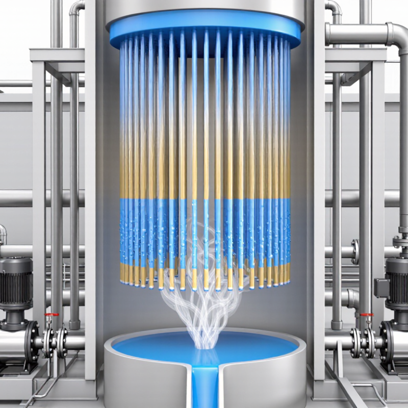
In a falling film evaporator, feed distribution determines how evenly liquid covers each vertical tube. Liquid enters the heating chamber through a top distributor. Small openings, channels, or spray devices guide it toward the tube walls. Gravity then draws the liquid downward as a continuous film. The practical target is usually a 0.1–1 mm layer.
A stable film must wet the entire inner circumference, not just one side. Poor distribution can leave dry patches near the tube entrance. Those patches may overheat, concentrate solids, and encourage fouling. Operators often inspect the distributor for blocked holes, uneven flow, and damaged edges. A clear liquid curtain is a useful visual sign, although it does not prove perfect wetting.
Flow rate, viscosity, tube diameter, and feed temperature all influence film thickness. Higher viscosity can produce a thicker, slower-moving layer. Excessive vapor movement may also disturb the liquid near the inlet. In practice, a carefully designed distributor may still perform poorly after installation. Small leveling errors matter. This is easy to underestimate. Regular checks should compare tube wetting, pressure drop, product concentration, and heating performance. If these readings disagree, the distribution system deserves attention before changing operating conditions.
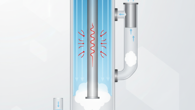
In a falling film evaporator, liquid feed enters through a distributor above the heated tubes. A distribution plate or spray nozzle spreads the feed around each tube entrance. Gravity then pulls the liquid downward along the inner tube walls. Instead of filling the tube, the feed forms a thin, continuous film. Steam or another heating medium warms the tube from outside. As the film travels, water or solvent evaporates and becomes vapor. The concentrated liquid continues downward, while vapor separates through a dedicated outlet.
Good distribution is the heart of stable operation. Dry patches reduce heat transfer and may encourage scaling. Excessive feed can create a thicker film, which slows evaporation. Film thickness also changes with viscosity, temperature, flow rate, and tube length. A thin film usually offers fast heat transfer and short residence time. However, very viscous feeds may not spread evenly. In practice, even a well-designed system can develop uneven wetting. That detail is easy to overlook. Regular inspection helps confirm whether the operating model matches reality.
Tips: Check distributor openings for blockage. Monitor outlet temperature and pressure together. Look for rising energy demand. A sudden change may indicate fouling, poor wetting, or unstable feed flow. Keep operating records; small trends often reveal problems earlier than alarms.
A falling film evaporator distributes liquid across the top of vertical heating tubes. Gravity pulls the liquid downward as a thin, continuous film. Steam condenses outside the tubes, while the liquid absorbs heat through the tube wall. As its temperature rises, part of the liquid flashes into vapor. The vapor and concentrated liquid leave the bottom separately.
The main target is strong heat transfer. With good wetting, clean surfaces, suitable steam pressure, and controlled feed flow, heat transfer coefficients may reach 1,000–4,000 W/m²·K. Thin films reduce thermal resistance. Turbulence also helps, especially when the liquid moves quickly through the tubes.
Lower residence time can protect heat-sensitive products. That detail matters in real operation.
Performance is less predictable with viscous feeds, suspended solids, or poor distribution. Dry patches create local overheating. Fouling adds resistance and slowly reduces capacity. Non-condensable gases can form an insulating layer on the steam side. Operators should monitor temperature differences, pressure drop, outlet concentration, and visual film behavior. A clean-water test may show excellent results, yet the actual process can perform worse. That gap deserves attention. The quoted coefficient must also be defined clearly, because local, liquid-side, and overall values are not interchangeable.
A falling film evaporator moves a thin liquid layer down heated tubes. Under vacuum, the liquid can boil at 40–80°C, depending on pressure and composition. This lower temperature protects heat-sensitive materials from harsh thermal exposure.
Feed distribution matters. A distributor spreads the feed across each tube entrance, where gravity and vapor flow shape the film. If the film breaks, local overheating and uneven concentration can follow.
As the liquid descends, water or another volatile component changes into vapor. The vapor rises toward a separator, while concentrated liquid continues through the lower outlet. Inside the separator, reduced velocity allows larger droplets to fall back. A mesh pad or vane section can capture finer droplets before the vapor reaches the vacuum line.
This is vapor–liquid separation in practical terms:
keep the vapor clean and the product contained.
Operators watch pressure, feed rate, temperature difference, and outlet concentration. A small pressure shift can change the boiling point and alter the separation load. Too much feed may flood the separator. Too little feed can dry parts of the tubes.
Real systems are less tidy than diagrams. Foam, dissolved solids, and sticky deposits may carry droplets into the vapor path. Design judgment matters here. Stable distribution, sufficient disengagement space, and controlled demisting must work together.
I would not treat 40–80°C as a fixed promise; actual performance requires testing the feed under operating vacuum. This caveat is easy to overlook.
Top How Does a Falling Film Evaporator Work
A falling film evaporator spreads feed liquid across heated tube walls. Gravity pulls the thin film downward. Heat then removes water as vapor. The concentrated liquid reaches the collector within seconds when distribution is even and heating is stable. Low residence time protects heat-sensitive products from prolonged thermal exposure. Operators can inspect the outlet for color changes, viscosity shifts, or burned deposits. These signs often reveal poor wetting before efficiency drops.
The “seconds” claim needs caution. Actual residence time depends on feed viscosity, tube length, pressure, temperature difference, and solids loading. A 2022 U.S. Department of Energy industrial report identified process heating as about 51% of industrial energy use. This makes efficient evaporation valuable, but energy savings depend on real operating conditions. The International Energy Agency also reported that industry used roughly 37% of global final energy in 2022. A properly designed falling film system can reduce unnecessary heat exposure and support better steam utilization. It cannot fix poor feed preparation.
Tips: Keep the feed distribution system clean. Measure film coverage, outlet solids, vacuum stability, and steam consumption. Do not trust one reading. Compare trends across several production cycles. Small changes in viscosity may require flow adjustment. And sometimes, the “fast” setting is too fast.
| Process Stage | Primary Function | Typical Operating Condition | Approximate Liquid Residence Time | Typical Heat-Transfer Medium | Typical Product Change | Key Control Point |
|---|---|---|---|---|---|---|
| 1. Feed Distribution | Spreads the incoming liquid evenly across the inner surface of the heating tubes. | Continuous feed; liquid film initiated at the tube inlet | Less than 1 second | Steam or hot water on the tube shell side | Feed enters as a relatively dilute solution with low viscosity. | Uniform wetting of every tube; poor distribution can cause dry spots and fouling. |
| 2. Falling-Film Formation | Gravity pulls the liquid downward as a thin, continuously renewed film. | Vertical tubes; downward flow under gravity | Approximately 1–5 seconds | Indirect heating through the tube wall | Large surface-area-to-volume ratio improves heat transfer and limits thermal exposure. | Stable film flow, adequate wetting rate, and controlled feed distribution. |
| 3. Rapid Evaporation | Heat supplied through the tube wall vaporizes part of the water or other volatile solvent. | Common product-side boiling range: approximately 45–85°C under vacuum | Approximately 1–10 seconds | Low- to medium-pressure saturated steam, depending on design | Solvent is removed while dissolved solids and nonvolatile components become concentrated. | Heat-transfer temperature difference, vacuum level, and boiling-point elevation. |
| 4. Vapor–Liquid Separation | Separates generated vapor from the concentrated liquid leaving the tube bundle. | Vertical or tangential separator operating under vacuum | Typically a few seconds | Usually no direct heating | Vapor exits toward condensation or the next effect; liquid continues toward collection. | Demister performance and vapor velocity must be controlled to reduce product carryover. |
| 5. Concentrate Collection | Collects the concentrated liquid in a separator sump or receiver for discharge or recirculation. | Concentrate temperature commonly about 45–85°C under vacuum | Approximately 2–15 seconds | Heat is maintained indirectly to avoid premature thickening. | Target total-solids concentration is reached, often within a single pass or a controlled recirculation loop. | Discharge rate, level control, viscosity, and prevention of solids settling. |
| 6. Final Discharge or Recirculation | Transfers concentrate to downstream processing or returns part of it to the evaporator for additional concentration. | Continuous flow with regulated pump or gravity-assisted discharge | Usually less than 30 seconds in the outlet section | Optional jacket or trace heating for viscous products | Product leaves at the specified concentration, viscosity, and temperature for the next operation. | Stable solids content, pumpability, and avoidance of excessive residence time. |
Note: Operating values are representative engineering ranges for falling-film evaporation systems. Actual conditions vary with feed composition, boiling-point elevation, viscosity, fouling tendency, required concentration, number of effects, and vacuum level.