Employment Application Apply
The 2026 Top Falling Film Evaporator Working Principle Guide explains how a thin liquid layer becomes concentrated under controlled heat and vacuum. The core mechanism is simple, but stable operation is not.
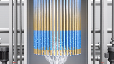
The working principle of falling film evaporator begins when feed liquid enters a distribution chamber above vertical heating tubes. A well-designed distributor spreads the liquid across each tube entrance. Gravity then pulls the liquid downward as a thin film. Steam or another heating medium condenses outside the tubes, transferring heat through the metal wall. As the liquid travels, part of its solvent flashes into vapor. The concentrated product and vapor leave the lower section, then enter a separator.
Small details matter. Uneven wetting can leave dry patches. Dry patches may cause local overheating, scaling, or product damage. Vacuum lowers the boiling temperature and helps protect heat-sensitive materials. However, excessive vapor velocity can disturb the film and carry droplets into the separator.
Process engineer Dr. James R. Couper describes the design priority this way: “Good evaporation begins with even distribution, not maximum temperature.” That principle remains practical on the plant floor. Operators often inspect spray patterns, pressure readings, and tube fouling before changing steam flow.
The process is efficient.
It is not effortless.
Viscosity, foaming, feed temperature, and solids content can shift performance quickly. A theoretical calculation may look convincing, yet field conditions can expose weaknesses. This guide therefore connects equipment geometry with operating experience, maintenance evidence, and measurable heat-transfer behavior. The result is a clearer, more reliable understanding of falling film evaporation in modern industrial systems.
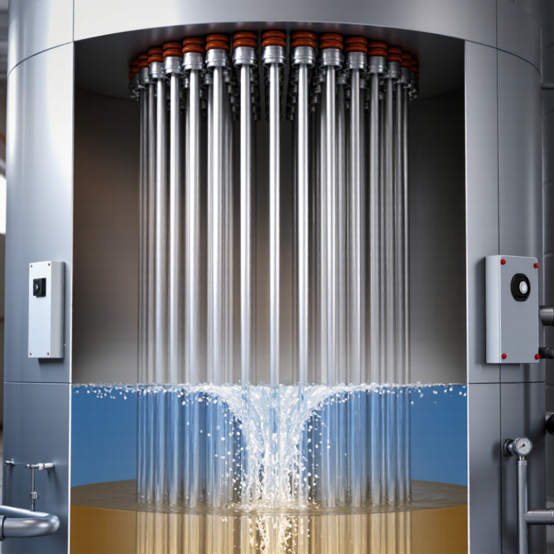
A falling film evaporator is a heat-transfer system that removes water from a liquid product. The liquid flows downward as a thin film along heated tube walls. Heat changes part of the liquid into vapor, while the concentrated product leaves the lower section. Thin film matters. It provides a large heating surface and reduces residence time. This design is useful for heat-sensitive liquids, but performance depends on stable distribution.
Core components include a feed inlet, distribution chamber, vertical heating tubes, steam chest, vapor separator, demister, concentrate outlet, and control instruments. The distribution chamber spreads feed across each tube entrance. Uneven flow can create dry patches, local overheating, or poor concentration control.
Heating steam transfers energy through the tube walls, while the vapor separator removes droplets from the vapor stream. A demister captures fine liquid carryover before vapor moves onward.
In operation, pumps, temperature sensors, pressure gauges, and flow controls work together. Operators should watch fouling, foam, vacuum stability, and product viscosity. A clean tube may perform well today and lose efficiency tomorrow. That assumption is often wrong. Real installations need inspection records and careful adjustment. Small changes in feed temperature or flow can alter film thickness noticeably. The evaporator is simple in principle, yet distribution remains the part most deserving of attention.
2026 Top Falling Film Evaporator Working Principle Guide
How a Falling Film Evaporator Operates Step by Step
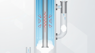
A falling film evaporator begins with a liquid feed entering a distribution chamber. The chamber spreads the feed across the tops of vertical heating tubes. Even coverage matters. A dry tube can overheat quickly. The liquid then moves downward as a thin film along each tube wall.
Heating steam usually surrounds the tubes, while the product flows inside them. Heat passes through the metal wall and raises the liquid temperature. Under vacuum, the liquid boils at a lower temperature. This helps protect heat-sensitive materials and reduces unnecessary energy use. Vapor forms inside the tubes as the film travels downward. The remaining liquid becomes more concentrated.
At the lower outlet, a separator removes vapor from the concentrated liquid. A demister can capture fine droplets before vapor leaves the vessel. The vapor may serve as heating energy for another effect. Sensors monitor pressure, temperature, feed rate, and concentration during operation. In field service, operators often adjust feed distribution before changing steam pressure. That small correction can stabilize the entire system.
A perfectly even film is an assumption, not a guarantee. Poor cleaning, uneven nozzles, or changing viscosity can disturb it. I would verify these conditions through inspection and trend data. Otherwise, a rising outlet temperature might be misread as better performance. Residual liquid then exits through the product line, while condensate leaves the heating side separately.
A falling film evaporator distributes liquid across heated tubes, where gravity creates a thin downward-flowing film. As water boils, vapor is separated from the concentrated liquid and commonly used as the heating medium for the next effect.
The chart shows representative conditions for a water-based four-effect system: vapor and boiling temperature decrease from the first effect to the last, while pressure is progressively reduced. Actual values depend on feed concentration, boiling-point elevation, heat-transfer area, fouling, vacuum equipment, and product requirements.
A falling film evaporator uses gravity to distribute liquid across heated tubes. The liquid forms a thin, fast-moving film. Steam condenses outside the tubes and supplies heat. As water flashes into vapor, dissolved solids become more concentrated. Heat transfer weakens when fouling thickens the surface or the film dries locally. The 2019 European Commission JRC BREF for Food, Drink and Milk Industries identifies evaporation as a significant thermal energy load.
Multiple-effect arrangements improve steam economy. The same BREF indicates that practical systems may reduce steam use to roughly 0.2–0.4 kilograms per kilogram of water removed, depending on effects, feed temperature, and product properties. These figures are not guarantees. Feed viscosity changes quickly near the outlet. Operators should monitor temperature difference, pressure, density, and flow together. One sensor rarely tells the full story.
Vapor separation protects product quality. A properly sized separator removes entrained droplets before vapor reaches the next effect or condenser. Mesh pads, centrifugal action, and controlled vapor velocity support this step. Poor separation can carry valuable solids away and distort concentration readings. Concentration control often combines inline density, refractive index, or conductivity measurement with automatic feed adjustment. A perfectly flat profile is rarely real. Dead zones, foaming, and sensor lag still create errors. The 2022 U.S. Department of Energy Industrial Decarbonization Roadmap also emphasizes process integration and heat recovery for reducing thermal demand.
2026 Top Falling Film Evaporator Working Principle Guide
A falling film evaporator spreads liquid across the inner walls of heated tubes. Gravity then pulls the thin film downward while heat converts part of the liquid into vapor. Thin films transfer heat quickly, but only when distribution remains even. A dry tube can overheat product and reduce operating stability.
Feed distribution is a critical design factor. Distributor holes, spray patterns, and inlet pressure must match the liquid’s flow rate and viscosity. Uneven wetting creates local fouling, especially with concentrated fluids. Small changes matter. During practical operation, operators often find that a clean distributor improves performance more than a larger heating surface.
Vacuum level also affects boiling temperature and product protection. A stable vapor separator prevents liquid carryover into downstream equipment. Tube diameter, length, material, and steam pressure should reflect the product’s sensitivity and solids content. Instrumentation should monitor temperature, pressure, feed rate, and differential pressure continuously. Cleaning access needs equal attention. A system that performs well during commissioning may lose efficiency after several cycles if deposits are ignored. This is an imperfect point in many designs: calculated heat-transfer values may look convincing, while real fouling behavior remains uncertain. Pilot testing and conservative safety margins provide more reliable decisions.
A falling film evaporator distributes liquid across the inner walls of vertical heating tubes. Gravity pulls the liquid downward as a thin film. Heating steam condenses outside the tubes, while water vapor leaves the product. Short residence matters. This design suits liquids that may lose quality under prolonged heating.
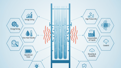
Common applications include dairy concentrates, fruit juices, plant extracts, wastewater streams, and pharmaceutical solutions. Operators value its low thermal exposure and efficient heat transfer.
Multiple-effect arrangements can reuse vapor between stages, reducing steam consumption.
In well-controlled systems, the product exits with consistent solids content and limited color change. These results depend heavily on stable feed distribution.
Operating limitations deserve equal attention.
Highly viscous liquids may form uneven films and transfer heat poorly. Foaming can carry product into the vapor line. Scaling gradually blocks heat-transfer surfaces and raises cleaning frequency.
A falling film unit also needs reliable vacuum control, correct tube wetting, and careful startup procedures.
A common mistake is assuming energy savings are guaranteed. Poor insulation, weak condensate removal, or fluctuating feed rates can erase the benefit.
Real plants often reveal this gap between calculated performance and daily operation.
Entry conditions should be tested, not guessed.